1. Overview
The primary mechanism for providing arguments to ShapeChange is the configuration file. A ShapeChange configuration file is an XML file which conforms to a custom XML Schema (ShapeChangeConfiguration.xsd).
The root element of the configuration file is the <ShapeChangeConfiguration> element. The file is then divided into various "functional elements" which are discussed separately in subpages.
The names of the elements are suggestive of their function:
-
The <input> element defines the source of the model and some parameters controlling its interpretation.
-
The optional <dialog> element specifies a GUI if one is present.
-
The optional <transformers> element defines which transformations shall be applied on the input model before target representations are created.
-
The <targets> element contains the configurations of each target format, such as XML Schema.
-
NOTE: Even though <targets> is typically used in a ShapeChange configuration, ShapeChange does not actually require the element to be present. An example where <targets> has been omitted is simply loading and thereby checking the input model.
-
-
The <log> element defines logging parameters.
ShapeChange supports XInclude, which allows for modularization of the configuration files. XInclude is by default used to incorporate various standardized sections (map entries, namespaces, stereotype aliases, etc.) into the configuration.
2. Processing Behavior
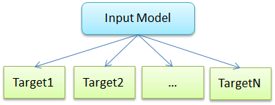
Per default, ShapeChange reads an input model and creates one or more target representations of it, for example XML Schema and feature catalogues.

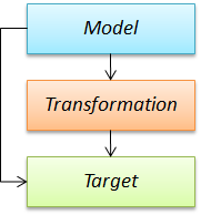
ShapeChange also offers to optionally perform a number of transformations on the input model, before creating the target representations on the result of these transformations.

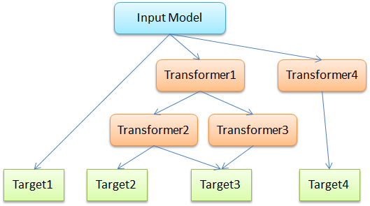
Transformations are not restricted to a single sequence. In fact, multiple transformations can be applied on the input model, and transformations can also be applied on the result of other transformations. Targets can be applied on the input model and/or the output of transformations. This results in a kind of tree-based processing model.

A sample configuration stub for the model shown in this diagram can look like this:
  1
2
3
4
5
6
7
8
9
10
11
12
13
14
15
16
17
18
19
20
21
22
23
24
25
26
27
28
29
30
31
32
33
34
35
36
37
38
39
40

  <ShapeChangeConfiguration>
    <input>
        <!-- ... -->
    </input>
    <transformers>
        <Transformer class="..."
            id="Transformer1" mode="enabled">
            <!-- ... -->
        </Transformer>
        <Transformer class="..."
            id="Transformer2" input="Transformer1" mode="enabled">
            <!-- ... -->
        </Transformer>
        <Transformer class="..."
            id="Transformer3" input="Transformer1" mode="enabled">
            <!-- ... -->
        </Transformer>
        <Transformer class="..."
            id="Transformer4" mode="enabled">
            <!-- ... -->
        </Transformer>
    </transformers>
    <targets>
        <Target class="..." mode="enabled">
            <!-- Target 1 ... -->
        </Target>
        <Target class="..." inputs="Transformer2"
            mode="enabled">
            <!-- Target 2 ... -->
        </Target>
        <TargetXmlSchema class="..."
            inputs="Transformer2 Transformer3" mode="enabled">
            <!-- Target 3 ... -->
        </TargetXmlSchema>
        <Target class="..." inputs="Transformer4"
            mode="enabled">
            <!-- Target 4 ... -->
        </Target>
    </targets>
</ShapeChangeConfiguration>